With Pentillion Construction, I delivered a custom glass awning replacement where the design intent was clean and visually simple, but the existing building made the installation much more complicated than the drawings suggested.
The project replaced existing vinyl awnings with a suspended glass canopy system supported by steel outriggers and diagonal tie rods. The challenge was making that system work on the real building, with the right tolerance, alignment, drainage, serviceability, and installation sequence.
The hidden structure did not match the clean drawing
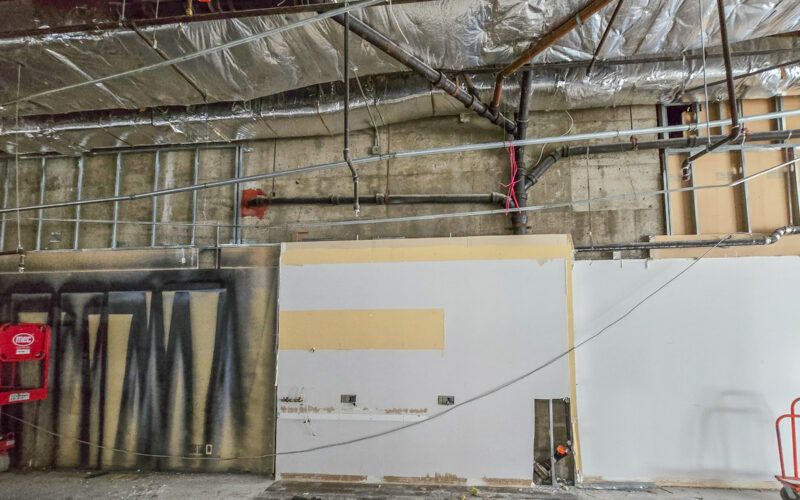
The upper tie-rod anchors were intended to connect back to the structural concrete spandrel beam, but that beam was hidden behind exposed-aggregate precast architectural panels with an inconsistent air gap behind them.
That changed the problem. The anchors could not simply be fastened as drawn, and the inconsistent gap made it difficult to scan the structure and confidently locate reinforcing steel before drilling. The installation needed enough field tolerance to avoid reinforcement while still leaving the finished awning visually aligned from the street.
Making the anchorage adjustable without looking like a fix
I helped investigate the existing condition and separate what was architectural cladding from what was part of the structural load path. That understanding shaped the redesign of the upper anchorage.
The detail needed to bridge through the architectural panel, connect back to the structure, and still allow the installer to shift final anchor locations where needed. The exposed cover plates then had to conceal that adjustment zone without looking like an afterthought.
The tie rods also had to stay visually aligned even when the hidden anchors had to move. The connection evolved toward a more adjustable arrangement using clevises and paired plates, with practical details such as wrench flats and opposite-handed threading so the rods could be adjusted in place.
Letting the glass layout respond to the building
The lower outriggers created another coordination problem. Their locations needed to avoid likely reinforcement while still supporting the glass layout. With the architect’s approval, the glass panel widths were allowed to vary within a controlled range so the steel supports could respond to the real structure instead of forcing a layout that was difficult to install.
The glass support detail also had to be reconsidered. A more fixed pressure-plate approach would have made installation and future service more difficult, especially if individual panels ever needed to be removed. Working with the installer, we moved toward a more serviceable approach that better suited how the glass would be handled, installed, and maintained.
Designing the corner so it could actually be fabricated
The corner conditions added another layer of practical design work. The corner framing had to coordinate glass sizes, steel fabrication, galvanizing, fit-up, and installation sequence.
I raised concerns about field welding galvanized steel and helped move the approach toward details that could be fabricated and installed more predictably. When galvanizing distortion became a concern, I helped look for a simpler framing approach that better matched the typical outriggers and reduced the risk of a distorted corner assembly.
Turning layout into a repeatable field process
A major part of my contribution was turning the layout problem into something the installer could repeat in the field. Because the outrigger and standoff locations varied along the building, there was no simple continuous datum for every cored opening.
I designed and 3D printed a positioning jig that sat on the installed outrigger and held a laser-cut template board for the core-hole locations. The template allowed the layout to shift when needed to avoid reinforcement while maintaining the relationship between the outrigger, standoff, and tie rod.
Dealing with drainage after the slope changed
The project also had to respond to drainage requirements. A late requirement changed the awning slope so water drained back toward the building rather than away from it.
That meant reviewing tie-rod geometry, glass slope, flashing, and gutter details so the finished system could manage water without creating maintenance or building-envelope problems. I helped develop a custom gutter approach that could be installed with the completed steel and glass while remaining serviceable and cleanable.
Keeping the work moving on site
Alongside the design and coordination work, I supported day-to-day site execution. That included coordinating with the architect, structural engineer, fabricators, glass contractor, sheet metal contractor, crane company, tenants, and site team; helping maintain scaffold access; developing site-specific safety procedures; removing existing awnings and flashing; coordinating electrical and signboard-related work; reviewing layout; resolving field discrepancies; and checking installation details as the work progressed.
A clear vision
The finished awning looks clean because we solved a lot of messy problems before they became visible. Hidden structure, reinforcement risk, anchor tolerance, glass layout, galvanizing, drainage, installation access, and future service all had to be handled together.
This project shows how I work between drawings and the field. I ask how an idea will be located, fabricated, adjusted, installed, drained, maintained, and handed off.